Fresnel Equations
As shown in Fig. 1, when light penetrates into different medium, how much will the incident light reflect and transmit? The reflection and transmitting of light that the equations predict is known as Fresnel reflection. Fresnel equations are expressed as follows, \begin{eqnarray} t_p &=& \frac{2 n_A \cos \alpha}{n_B \cos \alpha + n_A \cos \beta} = \frac{2 \sin \beta \cos \alpha}{\sin(\alpha + \beta)\cos(\alpha - \beta)} \\ r_p &=& \frac{n_B \cos \alpha - n_A \cos \beta}{n_B \cos \alpha + n_A \cos \beta} = \frac{\tan(\alpha - \beta)}{\tan(\alpha + \beta)} \\ t_s &=& \frac{2n_A \cos \alpha}{n_A \cos \alpha + n_B \cos \beta} = \frac{2 \sin \beta \cos \alpha}{\sin(\alpha + \beta)} \\ r_s &=& \frac{n_A \cos \alpha - n_B \cos \beta}{n_A \cos \alpha + n_B \cos \beta} = - \frac{\sin(\alpha - \beta)}{\sin(\alpha + \beta)} \end{eqnarray} where \( t_p \) and \( t_s \) are transmittances of p-polarized and s-polarized lights. Also, \( r_p \) and \( r_s \) are reflectances of p-polarized and s-polarized lights. In this page, the derivation of Fresnel equations is described.
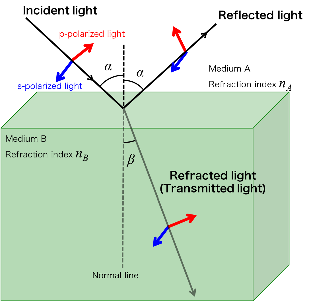
Figure 1. Incident, reflected and transmitted light
- Components parallel to the interface of the electric field and the magnetic field are equal at both ends of the interface
The magnetic and electric filed vector of
Incident wave + Reflected wave = Refracted wave
We will describe how to express the boundary condition by equations as below.
The direction of the magnetic and electric filed of incident, reflected, and refracted light are shown in Figure 2. (Note that the direction of the electric field is perpendicular to the direction of the magnetic field.)
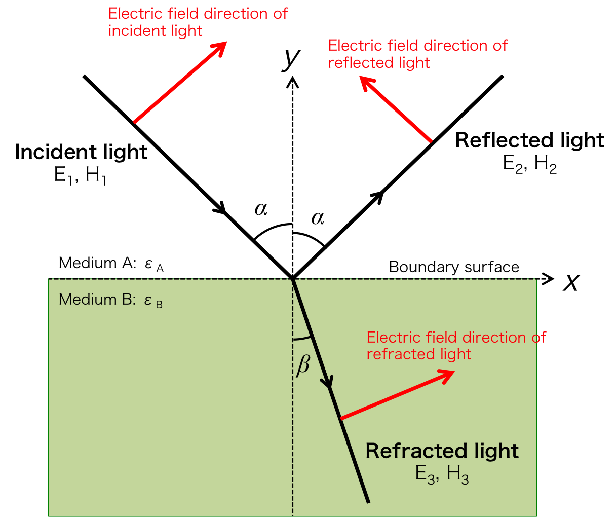
Figure 2. The reflection and refraction of the electric and magnetic filed
Here we try to express the boundary condition by equations. Since the magnetic field direction of the p-polarized light is parallel to the interface, relationship between \( H_{P1},\ H_{P2}\), and \(\ H_{P3} \), which are the magnetic field amplitude of incident, reflected and refracted light, can be expressed as \begin{eqnarray} H_{P1} + H_{P2} = H_{P3}\ \ \ \ \ \ \ \ \ \ \ \ \ (1) \end{eqnarray} In the same ways, since the electric field direction of the s-polarized light is parallel to the interface, relationship between \( E_{S1},\ E_{S2},\) and \( \ E_{S3} \), which are the electric field amplitude of incident, reflected and refracted light, can be expressed as \begin{eqnarray} E_{S1} + E_{S2} = E_{S3}\ \ \ \ \ \ \ \ \ \ \ \ \ (2) \end{eqnarray} On the other hand, perpendicular components of the magnetic field for s-polarized light and the electric field for p-polarized light are needed to resolved in a x direction and y direction. Referring Figure 2, we get \begin{eqnarray} H_{S1}\cos\alpha - H_{S2}\cos \alpha &=& H_{S3} \cos \beta \ \ \ \ \ \ \ \ \ \ \ \ \ (3) \\ E_{P1}\cos\alpha - E_{P2}\cos \alpha &=& E_{P3} \cos \beta \ \ \ \ \ \ \ \ \ \ \ \ \ (4) \end{eqnarray} Furthermore by using Maxwell's equations, we get \begin{eqnarray} H = \sqrt{\frac{\epsilon}{\mu}} E \ \ \ \ \ \ \ \ (5) \end{eqnarray} where \( \epsilon \) and \( \mu \) permittivity and permeability. Using equation (5), equations (1) and (3) can be written as \begin{eqnarray} \sqrt{\frac{\epsilon_A}{\mu_A}} E_{P1} + \sqrt{\frac{\epsilon_A}{\mu_A}} E_{P2} &=& \sqrt{\frac{\epsilon_B}{\mu_B}} E_{P3} \ \ \ \ \ \ \ \ \ \ \ \ \ \ \ \ \ \ \ (6) \\ \sqrt{\frac{\epsilon_A}{\mu_A}} E_{S1}\cos\alpha - \sqrt{\frac{\epsilon_A}{\mu_A}} E_{S2}\cos \alpha &=& \sqrt{\frac{\epsilon_B}{\mu_B}} E_{S3} \cos \beta \ \ \ \ \ \ \ \ \ \ \ \ \ (7) \end{eqnarray} where \( \epsilon_A \), \( \epsilon_B \), \( \mu_A \), and \( \mu_B \) are permittivity and permeability of medium A and B. If mediums A and B are not the magnetic material, then ratio of \( \mu_A \) to \( \mu_B\) can approximate as \begin{eqnarray} \sqrt{\frac{\mu_A}{\mu_B}} \sim 1 \end{eqnarray} From Snell's law, we get following relation \begin{eqnarray} \frac{\sin \alpha}{\sin \beta} = \sqrt{ \frac{\epsilon_B}{\epsilon_A} } \end{eqnarray} By substituting these relation to the equation (2), (4), (6) and (7), Fresnel equations are derived as follows, \begin{eqnarray} t_p &=& \frac{2 \sin \beta \cos \alpha}{\sin(\alpha + \beta)\cos(\alpha - \beta)} \\ r_p &=& \frac{\tan(\alpha - \beta)}{\tan(\alpha + \beta)} \\ t_s &=& \frac{2 \sin \beta \cos \alpha}{\sin(\alpha + \beta)} \\ r_s &=& - \frac{\sin(\alpha - \beta)}{\sin(\alpha + \beta)} \end{eqnarray}
Sponsored Link